
Bill of Material Manager
Overview
Inventor’s built‑in item numbering works only inside the current assembly. It assigns simple consecutive numbers and has no awareness of components shared across multiple models. When the same physical component appears in several assemblies—such as a structural column used in multiple systems—Inventor gives it a different item number in every file. This creates unnecessary detailing, duplicated shop work, redundant purchasing, and extra field tracking, even though the components are identical.
BOM Manager solves this by letting you assign mark numbers to custom iProperties stored directly on the component definitions. If you place all system assemblies into a single “system‑wide BOM” file—for example, dropping every column model from every system into one master BOM assembly—you can number each shared component once. That mark number then flows back to every system model automatically. Drawings can balloon the custom mark number, and the BOM stays consistent across the entire project.
BOM Manager also includes rule‑based numbering, eliminating the manual process of scanning a BOM and assigning prefixes or sequences by hand. You can define rules that automatically apply prefixes (such as PE‑ for purchased items), numbering ranges, or patterns based on descriptions or other properties. This ensures consistent, predictable numbering without manual effort.
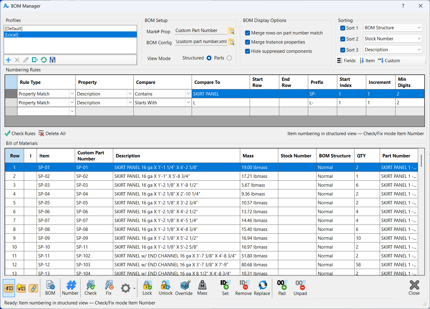
BOM Manager is a unified workspace for viewing, organizing, and controlling the Bill of Materials for the active assembly. It brings together all of the tools needed to inspect the BOM, apply numbering, validate consistency, and correct issues, all in one place. Instead of switching between multiple Inventor dialogs or manually editing item numbers, custom properties, or instance overrides, BOM Manager presents everything in a single, structured interface that mirrors the layout of the Inventor BOM while adding powerful automation and quality‑control features.
The tool is designed to help you maintain a clean, predictable, and fully consistent BOM. It supports both Structured and Parts Only views, and it reads the same data that Inventor uses for ballooning, merging, and row grouping. BOM Manager does not replace the Inventor BOM; instead, it enhances it by giving you clearer visibility, better control, and automated tools for numbering and validation. Any changes you make through BOM Manager are applied directly to the underlying components or BOM rows, so the results are immediately reflected in Inventor.
A key part of the interface is the BOM grid, which displays the BOM exactly as Inventor reports it, including row numbers, quantities, descriptions, and any custom fields you have defined. The grid highlights inconsistencies automatically, such as values that differ between occurrences or instance overrides that take precedence over definition‑level properties. This makes it easy to spot issues that would otherwise cause unexpected merging or balloon mismatches in drawings.
Above the grid, the form provides controls for sorting, numbering, rule‑based assignment, and BOM display options. These settings determine how the BOM is presented and how numbering operations behave. You can choose whether numbering writes to item numbers, custom part numbers, or instance overrides, and you can define rules that assign prefixes and sequences based on row conditions. The Check and Fix tools analyze the BOM for missing or conflicting numbers and can automatically correct them while preserving your numbering style.
BOM Manager also includes a full profile system that allows you to save and restore all of your settings. Profiles capture the entire configuration of the form, including numbering mode, sorting fields, merge options, rules, and BOM setup. This makes it easy to switch between different workflows or standardize settings across projects. The only data not stored in profiles is the BOM content itself, since that comes from the active assembly.
Overall, BOM Manager provides a complete environment for preparing, validating, and maintaining the Bill of Materials. Whether you are numbering a new assembly, cleaning up a legacy project, or ensuring that your BOM matches company standards, the tool gives you the visibility and control needed to produce consistent, reliable results.
Profiles
Profiles allow you to save and restore the complete configuration of the BOM Manager form. Every setting that controls how the BOM is displayed, sorted, numbered, and processed is stored inside a profile so you can return to a known setup at any time. This includes all options in BOM Setup, all display and merge settings, all sorting fields and directions, the entire rules table, the numbering mode, and every other user‑controlled option on the form. The only thing a profile does not store is the BOM data itself, since that always comes from the active assembly.
Profiles are especially useful when you work with different customers, standards, or project types. You can create a profile for each workflow and switch between them instantly. For example, you might have one profile that uses custom part numbers with a specific prefix structure, another that uses instance numbering for fabrication drawings, and another that uses simple item numbers for internal documentation. Loading a profile restores the entire environment exactly as it was when you saved it, ensuring consistency and eliminating the need to reconfigure the form each time.
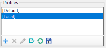
Two profiles are always present in the list. The Default profile is a clean starting point that represents a neutral configuration. It cannot be deleted and serves as a fallback if you need to reset the form. The Local profile is stored inside the assembly file itself. This allows each assembly to carry its own preferred BOM Manager configuration, which is useful when different assemblies require different numbering rules or display settings. The Local profile is also permanent and cannot be removed.
You can add new profiles at any time. When you create a profile, the current state of the entire form is captured and stored under the name you provide. Renaming a profile changes only its name, not its contents. Deleting a profile removes it from the list permanently, except for Default and Local, which are protected. The Copy To command lets you overwrite an existing profile with your current settings, making it easy to update a profile as your workflow evolves.
Profiles make BOM Manager predictable and repeatable. Once you have a configuration that works for your process, you can preserve it, reuse it, and share it across projects without having to remember which options were set or how the rules were arranged. They are the foundation for consistent BOM preparation and numbering across your entire workflow.
These commands appear on the toolbar directly below the profile list and are used to manage the creation, editing, and maintenance of all saved profiles.
Add Profile
Click to create a new profile. All current BOM Manager settings are copied into the new profile, including numbering mode, sorting, display options, and rule definitions. Enter a name to save the profile so it can be reused for future projects or workflows.
Delete Profile
Click to remove the selected profile from the list. All saved configuration settings in that profile are permanently deleted. The Default and Local profiles cannot be removed, since they are required system profiles. Use this option to clean up unused or outdated profiles.
Rename Profile
Click to change the name of the selected profile. The underlying settings remain unchanged; only the profile name is updated. This is useful for clarifying workflow‑specific profiles, such as distinguishing different customer standards or project types.
Copy To
Click to overwrite the selected profile with the current form settings. This saves your latest numbering, sorting, display, and rule configuration into that profile so it can be restored later.
Reload Profile
Click to reload the selected profile from memory, discarding any unsaved changes made during the current session. This restores the profile to the last saved state without affecting the version stored on disk.
Revert to Disk
Click to reload the selected profile from disk, discarding all changes made since the dialog was opened. This restores the profile exactly as it existed when BOM Manager was launched.
Settings
BOM Setup
The BOM Setup group defines the core context that BOM Manager uses when reading and interpreting the Bill of Materials. These settings determine which BOM view is used, which custom property is treated as the numbering target when working in Custom or Instance modes, and which column layout is applied to the BOM grid. Because these choices affect almost every operation in the tool, they are saved as part of each profile so that your preferred configuration is always restored automatically.
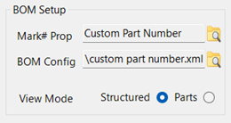
The Custom Property Name field identifies the iProperty that BOM Manager will use when numbering in Custom mode or when applying instance overrides. This must be a valid property name that exists on the components you intend to number. When you select a custom property here, all numbering operations that target custom numbers will write to this field. If the property does not exist on a component, Inventor will create it automatically when the number is assigned. Choosing the correct custom property name is essential for maintaining consistent numbering across your assemblies.
The BOM Config File field allows you to assign a saved BOM column layout exported from Inventor. Inventor’s BOM editor lets you customize which columns appear, how they are ordered, and how they are formatted. You can export that configuration to an XML file, and BOM Manager can load it here. When a BOM config file is assigned, the BOM grid in BOM Manager will always use that layout, ensuring that your view remains consistent across projects and matches your company standards. If no file is assigned, the grid uses the current Inventor BOM definition.
The View Mode setting determines whether BOM Manager reads the Structured view or the Parts Only view of the BOM. Structured view preserves the assembly hierarchy and shows subassemblies as separate rows. Parts Only view collapses the structure and lists only physical components. Many numbering operations depend on which view is active, since the row order and grouping can change significantly between the two. Selecting the correct view mode ensures that numbering, sorting, and rule evaluation behave as expected.
Together, these settings establish the foundation for how BOM Manager interprets and displays the Bill of Materials. Once configured, they rarely need to be changed, and profiles make it easy to preserve them for future sessions or different workflows.
BOM Display Options
The BOM Display Options control how the BOM grid is filtered and how certain rows are combined before numbering or rule evaluation. These settings mirror the options available in Inventor’s BOM editor, and they determine which components appear in the grid and how they are grouped. Because these are Inventor behaviors, users who need deeper technical details can refer to the Inventor help system, but the descriptions here explain how they affect BOM Manager.
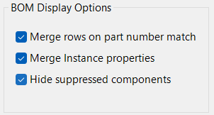
Merge rows on part number match combines rows that share the same part number into a single BOM row. This is the same behavior Inventor uses when identical components are treated as a single item. When this option is enabled, BOM Manager will show one row for all components that share the same part number, and numbering operations will treat them as a single unit. When it is disabled, each occurrence or definition appears separately, even if the part numbers match.
Merge instance properties controls whether instance‑level overrides are merged into the displayed row. When enabled, BOM Manager will combine instance values into the row and highlight any differences so you can see where overrides exist. When disabled, instance‑level variations are not merged, and the row reflects only the definition‑level values. This option is useful when you want to see whether instance overrides are affecting your BOM or causing unexpected variations.
Sorting
The Sorting group controls the order in which rows appear in the BOM grid. It works the same way as Inventor’s built‑in sorting tools, so the behavior will be familiar to anyone who has used the BOM editor. You can define up to three sort levels, each with its own field and an ascending checkbox. The first sort field determines the primary order, the second is used when two rows match on the first field, and the third is used only when the first two fields are identical.
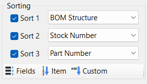
Each sort field has a matching ascending checkbox. When the box is checked, the field is sorted in ascending order. When it is unchecked, the field is sorted in descending order. This gives you full control over how the BOM is arranged, whether you want alphabetical descriptions, numeric item numbers, or custom property values arranged in a specific sequence.
Below the sort fields are three shortcut buttons that apply common sorting patterns without requiring you to choose fields manually. Sort By Fields uses the three fields you selected above. Sort By Item sorts the BOM by item number, matching Inventor’s default behavior. Sort By Custom Part Number sorts by the custom property defined in the BOM Setup section. These shortcuts make it easy to switch between different sorting styles as you work.
All sorting settings, including the selected fields, the ascending options, and the last used sort button, are saved in profiles. This ensures that your preferred sorting order is restored automatically whenever you load a profile or return to a project.
Numbering Rules
Numbering rules define how mark numbers are assigned throughout the BOM. Instead of manually entering numbers or relying on simple sequential numbering, rules allow you to automate the entire process based on the conditions of each row. When you run the Number command, BOM Manager evaluates each row against the rules you have defined and assigns numbers according to the first rule that matches. This creates a predictable, repeatable numbering system that adapts to the structure and content of the assembly.
Rules operate on the current numbering mode, which determines where the assigned numbers are written. In Item mode, rules assign values to the BOM item number. In Custom mode, they write to the custom property defined in the BOM Setup section. In Instance mode, they write to instance‑level properties on each occurrence. The rules themselves do not change based on the mode, but the destination of the assigned number does. This makes it possible to use the same rule set for different numbering workflows simply by switching modes.
Each rule describes a condition that determines which rows it applies to. Conditions can be based on row ranges, property values, custom properties, BOM structure, or numeric comparisons. When a row meets the condition, the rule assigns a prefix, a starting index, and an increment pattern to generate the final number. Because rules are evaluated from top to bottom, the order of the rules determines which one applies when multiple rules could match the same row.
Numbering rules give you fine‑grained control over how mark numbers are generated. They allow you to group similar components together, apply different prefixes to different categories of parts, and maintain consistent numbering patterns across large assemblies. Once defined, rules can be saved in profiles so they can be reused across projects without having to recreate them.
Rule table structure
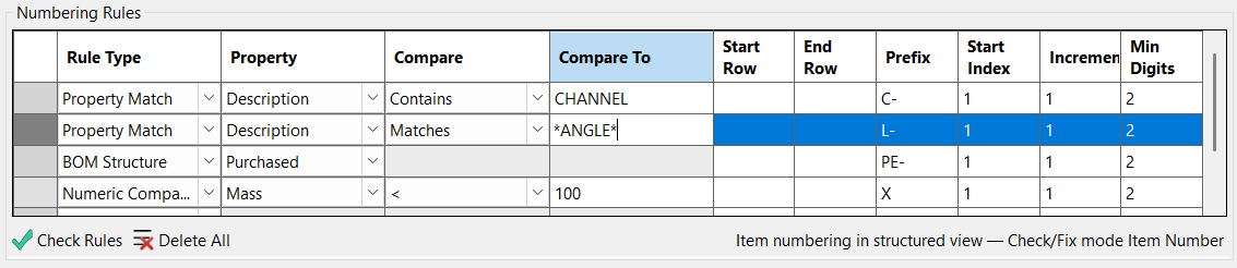
The rules table defines the structure of each numbering rule and controls how numbers are generated when the Number command is run. Each row in the table represents a single rule, and each column describes a specific part of that rule. Together, these fields determine which BOM rows the rule applies to and how the final number is constructed. The table is evaluated from top to bottom, so the order of the rules is just as important as their content.
Every rule begins with a rule type, which determines how the rule decides whether it applies to a particular BOM row. Depending on the type, additional fields become relevant. For example, a property‑based rule uses the Property and Compare fields, while a manual range rule uses the row range fields. The rule type sets the overall behavior, and the remaining columns supply the details needed to evaluate the condition.
The Property and Compare fields are used when the rule type involves matching a property value. The Property field identifies which BOM column or custom property the rule should examine. The Compare field defines how the value is tested, such as checking for equality, inequality, or numeric relationships. The Compare To field provides the value or threshold that the rule uses when performing the comparison. These three fields work together to determine whether the rule applies to a given row.
Once a rule matches a row, the remaining fields control how the number is generated. The Prefix field allows you to add a fixed string before the numeric portion of the number. The Start Index defines the first number assigned by the rule, and the Increment field determines how the number increases for each subsequent row that matches the same rule. The Min Digits field controls the minimum number of digits in the numeric portion, allowing you to enforce leading zeros when needed. These fields give you full control over the format and progression of the numbers produced by the rule.
The rules table is flexible enough to support simple sequential numbering, complex category‑based numbering, or anything in between. By combining rule types, property comparisons, prefixes, and numeric patterns, you can create a numbering system that matches your company standards and adapts automatically to the structure of your assemblies.
Rule types
Rule types determine how each rule decides whether it applies to a particular BOM row. Each type represents a different way of matching rows, and choosing the correct type is the key to building a numbering system that behaves the way you expect. When the Number command runs, BOM Manager evaluates each row against the rules in order, and the first rule whose type and conditions match the row is the one that assigns the number.
The simplest rule type is the manual range rule. This type applies to rows based solely on their position in the BOM grid. You specify a starting row and an ending row, and any row within that range will use the rule. Manual range rules are useful when you want to number a specific block of rows in a fixed order, regardless of their properties.
Property‑based rules allow you to match rows based on the value of a standard BOM property. You choose a property such as Description, Part Number, Material, or any other column available in the BOM. The rule then compares that property to a value you specify. If the comparison succeeds, the rule applies. This type is ideal for grouping similar components together, such as assigning a prefix to all purchased parts or numbering all components with a specific material.
Custom property rules work the same way as property‑based rules but operate on user‑defined iProperties instead of standard BOM fields. These rules are useful when your organization uses custom metadata to categorize components, such as manufacturing codes, department tags, or classification fields. By matching on custom properties, you can build numbering systems that reflect your internal standards.
BOM structure rules match rows based on their BOM structure setting, such as Normal, Purchased, Inseparable, or Reference. This allows you to assign different numbering patterns to different structural categories. For example, you might want all purchased components to share a prefix or all inseparable components to follow a specific sequence.
Numeric comparison rules allow you to match rows based on numeric values such as mass, volume, area, or any numeric property. These rules compare the property to a threshold using greater‑than, less‑than, or equality tests. Numeric rules are useful when you want to separate components by size, weight, or other measurable characteristics.
Each rule type provides a different way to target rows, and by combining them, you can create a flexible and powerful numbering system. Whether you need simple sequential numbering or a highly structured scheme based on multiple criteria, the available rule types give you the tools to define exactly how numbers should be assigned.
Rule workflow
The rule workflow describes how BOM Manager evaluates the rules table and applies numbering to the BOM. When you run the Number command, the tool processes the BOM from top to bottom and checks each row against the rules in the order they appear. As soon as a row matches a rule, that rule assigns the number, and no further rules are considered for that row. This “first match wins” behavior is the foundation of the entire system, and it allows you to control numbering by arranging rules in a logical sequence.
Creating a rule is as simple as adding a new row to the table and selecting the appropriate rule type. Once the type is chosen, the relevant fields become active, and you can enter the conditions and numbering pattern you want the rule to use. Editing a rule works the same way; you simply change the values in the row. Because rules are evaluated in order, moving a rule higher or lower in the list can dramatically change how numbering behaves. For example, a broad rule placed too high may catch rows that were intended for a more specific rule below it.
As the rules are evaluated, each matching row receives a number based on the prefix, starting index, increment, and minimum digit settings defined in the rule. If multiple rows match the same rule, the numbering continues to increment for each row until a different rule is encountered. This allows you to create grouped numbering patterns, such as assigning one sequence to purchased parts and another to fabricated components, all within the same assembly.
The workflow is designed to be predictable and transparent. You can review the rules at any time, adjust their order, refine their conditions, or change their numbering patterns. Because the rules table is saved in profiles, you can build a numbering system once and reuse it across multiple assemblies without having to recreate the logic. This makes the rule workflow a powerful tool for maintaining consistent numbering standards across your entire project or organization.
Check Rules and Delete All
The Check Rules command verifies that every rule in the table is valid and complete before you attempt to number the BOM. It examines each rule row and confirms that the required fields are filled in, that the rule type is compatible with the fields being used, and that the values entered make sense for the type of comparison being performed. This helps prevent situations where a rule might never match, might match incorrectly, or might produce unexpected numbering results. Running Check Rules is especially useful after making several edits or when building a new rule set from scratch.
When the check is complete, the tool reports any issues it finds so you can correct them before numbering. These issues might include missing values, invalid comparisons, or conflicting rule definitions. The goal is to ensure that the rules behave predictably and that the numbering process runs smoothly. Although you can number without checking the rules first, using this command helps catch mistakes early and reduces the chance of having to renumber the BOM later.
The Delete All command clears the entire rules table in a single action. This is useful when you want to start over with a clean slate or when switching to a completely different numbering strategy. Because rules are often saved in profiles, deleting all rules does not affect any saved profiles unless you explicitly overwrite them. This makes it easy to experiment with new rule sets without losing your established configurations.
Together, Check Rules and Delete All provide a simple way to maintain the integrity of your rule set. One ensures that your rules are valid and ready to use, while the other allows you to reset the table quickly when needed. Both commands help keep the numbering workflow clean, predictable, and easy to manage.
BOM Data
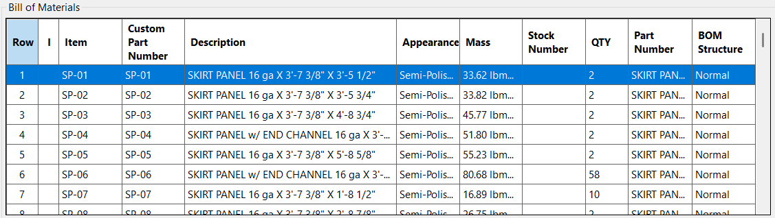
The BOM Data section displays the Bill of Materials exactly as Inventor defines it, using the same columns, structure, and row ordering that appear in the Inventor BOM editor. The grid is read‑only, which ensures that all edits to the BOM continue to flow through Inventor’s own tools and property system. BOM Manager’s role is to present the data clearly, highlight inconsistencies, and provide a controlled environment for numbering and validation without altering the underlying BOM structure.
Each row in the grid corresponds to a row in the active BOM view, whether you are working in Structured or Parts Only mode. The grid includes a dedicated row number column that shows the position of each row in the current sort order. This row number is not an item number; it is simply a reference index that helps you understand how rules, sorting, and numbering will apply as you work. Next to the row number, the grid displays whether the row is virtual, locked, or both. Virtual rows represent components that do not physically exist, and locked rows are protected from changes to their item numbers. These indicators help you understand how each row will behave during numbering and other operations.
The grid also highlights inconsistent or varying data so you can quickly identify potential issues. If a property differs between occurrences of the same component, the affected cells are marked to show that the value varies. Instance overrides are also highlighted so you can see when an instance‑level value is taking precedence over the definition‑level property. These visual cues make it easier to diagnose problems that could lead to unexpected merging, balloon mismatches, or incorrect numbering.
The columns shown in the grid come directly from the Inventor BOM definition. If you want to change which columns appear, their order, or their formatting, you make those changes in the Inventor BOM editor. Inventor allows you to export a BOM configuration file that captures your column layout. By assigning that file to the BOM Config setting in BOM Manager, you can ensure that the grid always uses the same layout, regardless of the assembly you are working on. This keeps your BOM view consistent across projects and aligns it with your company standards.
Overall, the BOM Data section provides a clear, accurate, and consistent view of the assembly’s Bill of Materials. It serves as the foundation for sorting, rule evaluation, numbering, and validation, giving you full visibility into the structure and content of the BOM before making any changes.
Virtual and locked rows
Virtual and locked rows are special indicators that help you understand how each component behaves during numbering and other BOM operations. These indicators appear in their own column in the BOM grid so you can immediately see which rows are affected. Because these behaviors come directly from Inventor, BOM Manager reflects them exactly as Inventor defines them, ensuring that numbering and validation remain consistent with the underlying model.
A virtual row represents a component that does not physically exist in the assembly. Virtual components are often used for reference, placeholders, or logical grouping. Since they are not real parts, they cannot receive instance numbers and may behave differently during numbering depending on the mode you are using. BOM Manager marks these rows with a V so you can easily identify them and understand how they will be treated during numbering and rule evaluation.
A locked row indicates that the item number for that component has been manually locked in Inventor. When a row is locked, its item number cannot be changed by BOM Manager, even if a rule or numbering operation would normally assign a new value. Locked rows are marked with an L in the grid. This helps you avoid confusion when a numbering operation appears to skip a row or when a rule does not seem to apply. The lock ensures that the item number remains fixed unless you unlock it manually in Inventor.
Some rows may be both virtual and locked, and these are marked with V/L. This combination is uncommon but possible, especially in assemblies that use virtual components for planning or documentation. When a row is marked V/L, it inherits the behavior of both categories. It will not receive instance numbers, and its item number cannot be changed. Seeing this indicator helps you understand why certain numbering operations may not affect that row.
These indicators provide clarity when working with complex assemblies. By showing which rows are virtual, locked, or both, BOM Manager helps you anticipate how numbering, sorting, and validation will behave, reducing surprises and making the BOM easier to manage.
Commands
The command buttons are located on the toolbar at the bottom of the form. These commands operate on the current BOM view, numbering mode, and selected row range, and they provide the primary tools for numbering, validating, and managing BOM data within the dialog.
Numbering mode buttons
The numbering mode buttons determine where BOM Manager writes numbers during all numbering, prefix, padding, and correction operations. Only one mode can be active at a time. Item mode writes directly to the BOM item number. Custom mode writes to the custom property defined in BOM Setup. Instance Override mode writes to instance‑level properties on each occurrence. The active mode controls how numbering behaves and which fields later commands operate on.
BOM
The BOM command opens Inventor’s native Bill of Materials editor. Use this when you need to change column visibility, reorder columns, adjust formatting, or export a BOM configuration file. Any changes made in the Inventor BOM are reflected immediately in BOM Manager, since the grid always displays the BOM exactly as Inventor defines it.
Number
The Number command applies the rules table to the current BOM view and assigns numbers according to the active numbering mode. Each row is evaluated in order, and the first matching rule determines the assigned number. If no rules are defined, the command performs simple sequential numbering. All results are written directly to the item number, custom property, or instance override field depending on the selected mode.
Check and Fix
The Check and Fix command analyzes the current BOM for numbering and row‑consistency issues and can automatically correct them based on the selected Check/Fix mode. It evaluates the BOM using the same logic Inventor uses for ballooning, merging, and row grouping, ensuring that the numbers you see in the BOM match the numbers Inventor will use in drawings. The tool detects missing numbers, duplicates, conflicting values within a row, and inconsistencies that would cause unexpected merging or balloon mismatches. When fixing is enabled, the tool resolves these issues by assigning new numbers, removing or normalizing instance overrides, and updating custom numbers as needed, all while preserving your existing numbering style, prefixes, separators, and digit formatting. Non‑numbering issues—such as mismatched descriptions, stock numbers, or mass—are always reported but never changed automatically. The result is a clean, consistent BOM that behaves predictably in both the assembly and drawing environments.
Check and Fix provides detailed reporting for every issue it finds and every change it makes. In Check mode, the report lists all numbering conflicts, missing values, mismatched properties, and any rows that cannot be evaluated under the selected mode. In Fix mode, the report also includes a complete record of all corrections applied, such as assigned numbers, removed overrides, normalized values, and any rows that were skipped because they cannot be fixed automatically. All results are grouped by mark number so related issues appear together, and rows with missing numbers are grouped separately for clarity. This structured reporting makes it easy to understand what was wrong, what was corrected, and what still requires manual attention.
Check/Fix mode (gear)
The Check/Fix mode menu controls how numbering is interpreted and corrected during Check and Fix operations. Item mode works strictly with item numbers stored in the BOM. Effective mode follows Inventor’s ballooning logic: it uses the instance override if one exists, otherwise the custom number, and treats virtual components as using only their custom number. Strict Custom mode enforces definition‑level numbering by requiring every component file to have a consistent custom number and ignoring all instance overrides. Strict Instance mode enforces occurrence‑level numbering by requiring every occurrence to have an instance override; virtual components cannot satisfy this requirement and are reported as errors. The selected mode determines how numbering is evaluated, how conflicts are resolved, and which fields are updated during fixing.
Lock, Unlock, Clear Overrides
These commands modify numbering behavior for a selected range of BOM rows. Each command prompts you for a start row and end row, allowing you to target exactly the portion of the BOM you want to update. Lock assigns a fixed item number to the selected rows so numbering operations cannot change them. Unlock removes those locks, allowing the rows to participate normally in numbering. Clear Overrides removes instance‑level number overrides from the selected rows, restoring their effective number to the underlying custom number. All three commands respect the active numbering mode and BOM view, ensuring that changes apply consistently within your current workflow.
Update Mass
The Update Mass command refreshes mass properties for all components in the current BOM view, using the same calculation logic as Inventor’s built‑in Update Mass Properties command. This ensures that mass‑based fields—such as Mass, Volume, and any rules or checks that depend on them—reflect the latest geometry and are fully up to date before numbering or validation.
Set, Remove, Replace Prefix
These commands modify the prefix portion of the numbering field defined by the active numbering mode. Each command prompts you for a start row and end row so you can apply the change to a specific range of BOM rows. Set Prefix applies a new prefix to all numbers in the selected range. Remove Prefix strips the existing prefix from each number without altering the numeric portion. Replace Prefix updates only the prefix portion by replacing an old prefix with a new one, preserving the rest of the number. These tools make it easy to standardize numbering across a project, adjust naming conventions, or correct inconsistent prefixes while keeping the underlying numbering intact.
Pad and Unpad
These commands adjust the numeric portion of the selected numbering field by adding or removing leading zeros. Each command prompts you for a start row and end row so the change applies only to the rows you specify. Pad Digits increases the width of the numeric portion by adding leading zeros, helping align numbers visually or match a required numbering format. Unpad Digits removes unnecessary leading zeros while preserving the underlying numeric value. Both commands operate only on the numeric portion of the number and leave prefixes, separators, and suffixes unchanged.
Examples
Example: Configure and save a standard BOM profile
To create a reusable BOM configuration, begin by setting up the options in the BOM Setup section, including the custom property name, BOM configuration file, and preferred view mode. Adjust the Display Options to control how rows are merged, how instance properties are handled, and whether suppressed components are shown. Define your preferred sorting order using the Sort By fields, then build your numbering rules by adding conditions, prefixes, and formatting requirements that match your project standards. Once all settings are in place, open the Profiles toolbar and click Add Profile. Enter a name for the new profile and save it. The complete configuration—including setup, display behavior, sorting, and rules—can now be recalled instantly for future assemblies.
Example: Number an assembly from scratch
To number an assembly for the first time, begin by defining your rules in the Rules table. Add conditions that identify each type of component you want to number, then assign prefixes, formatting, and sequence behavior that match your project standards. Once the rules are in place, choose the numbering mode—Item, Custom, or Instance—to control where new numbers will be written when you run the Number command.
After the rules and numbering mode are set, click Number to apply the rules to the current BOM view. The tool assigns numbers row by row, following your rule order and writing values into the appropriate fields based on the selected numbering mode. When numbering is complete, run Check using one of the four Check/Fix modes—Item, Effective, Strict Custom, or Strict Instance—to verify that all rows are consistent, unique, and aligned with Inventor’s merging and ballooning logic. If any issues are reported, run Fix to automatically correct them. Fixing resolves conflicts, assigns missing values, removes or normalizes overrides, and preserves your numbering style so the final BOM is clean, predictable, and ready for downstream use.
Example: Align BOM with an existing BOM config
To match your BOM to an established company or project standard, begin by exporting a BOM configuration file directly from Inventor’s BOM editor. This file captures the column layout, visibility, order, formatting, and merge behavior used in that environment. In BOM Manager, click the BOM Config button and locate the exported file. As soon as you select it, the configuration is applied automatically. The BOM grid immediately updates to match the Inventor layout, ensuring that columns, merge rules, and display behavior are consistent with the standard you exported.
Aligning your BOM with an existing configuration ensures that your numbering rules, checks, and fixes operate on the same structure used in Inventor. This eliminates discrepancies between environments, prevents unexpected merging or missing columns, and guarantees that downstream drawings and documentation follow the same conventions as the source BOM.
Assembly Tool Suites